Wednesday 2 March 2011

Extruder

Quick post to show off the extruder nozzle I machined!

Brass M6 nut for comparison

0.508mm hole!
The process of making it:

  1. Start with a length of 10mm brass rod
  2. Using this as a guide I machined (on a hobby lathe) the outer dimentions
  3. Using a pin vice to hold the tiny drill bit (number 76 twist drill bit), and a jacobs chuck to hold the pin vice i drilled the hole to a depth of around 3-4mm. I set the lathe to the fastest it would go.. which was around 900 RPM.
  4. I then flip the brass around in the clamp and drill out the inside diameters 
  5. I then tapped the external and internal threads (M6 external, M8 internal)

Sunday 20 February 2011

Wiring it up!


Having studied mechanical engineering I felt very comfortable designing, making and tweaking the hardware of huxley; but connecting the whole lot up to a computer to make it print was quite a step into the unknown!

I chose to use gen6 electronics from mendel-parts.com to help simplify this problem. It only uses one circuit board, which has a footprint of around 110x60mm, and make life connecting up all the components really simple.

Power

To power the unit I used a laptop charger, cut off the power jack and put the positive wire into the the positive side of the supplied connector, and negative to negative. Use the following picture as a guide but make sure you check the polarity with a multimeter as any mistakes will ruin your shiny new board! Also be sure to check that the power supply is rated between 12v and 24v and the correct wattage.

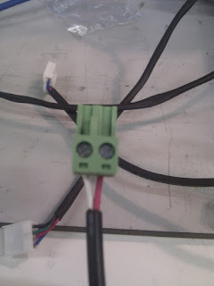
Wiring of the power connector
I would like to incorporate a emergency stop into the system too. This will most likely just cut all power to the gen6 board, but i could be really useful in situations when an opto flag bends or something else goes wrong!


Opto Switches
There was an option to buy pre-wired opto switches alongside the gen6 electronics which I bought to save the hassle of doing it myself. This worked as all i had to do was attach them to Huxley and plug the other end into the appropriate plug on the GEN6 board. The tricky part was physically attaching the opto switches to points on Huxley... The pictures below show how I mounted them (only on the x-axis for now!):

Reverse View of Opto mount

Front view (note that the trigger is mounted to the x-carriage)


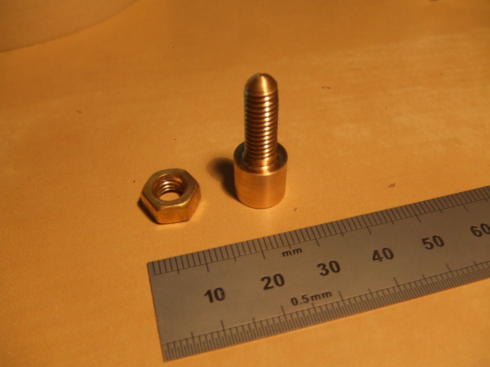
The Z-axis proved most tricky as it needed to be placed exactly in the right position to trigger when the extruder tip is around one layer thickness away from the build surface. I used a length of M3 threaded rod to secure the opto switch to the drive side of the z-axis. The threaded rod allowed the opto switch to be positioned at the correct height.. The only problem is that it is not secured very well, a small knock would rotate the opto causing the extruder tip to come crashing down!

Stepper Motors
I bought the stepper motors from zapp automation, 3xNEMA 14 (for the axes) and 1xNEMA17 (for the extruder). I bought the steppers with the highest holding torque rating to hopefully minimise the possibility of skipping.


NEMA 17 Motor for the extruder

I did not buy the molex connectors from mendel-parts (forgot!), so i decided to use floppy disk power connectors from maplins which did the job very well (although I had to cut a bit of the connector off to make it fit!). I also bought some heat shrink wrap to tidy up the wires.
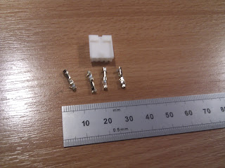
Floppy disk power connector with terminals
Stepper motor wires: soldered and shrink wrapped
The order of the wires had me stumped for a while, but I found this post in the mendel-parts forum. From left to right: blue - red - green - black.

When using the repsnapper software there is an option to control the steppers individually, this is very handy to find out if you have wired up the motors correctly. Hitting the - button (eg -0.1) then the axis should move towards the opto switch, if the axis goes the other way you need to reverse the order of the wires (so from left to right: black - green - red - blue). Pressing home on the same menu moves the axis in the negative direction until the opto switch is flagged. So be sure your optos are setup correctly before this or there will be some serious crunching!


Software
The Downloads section of mendel-parts.com has the majority of necessary downloads. Firstly I got drivers;  this sets up a USB->Serial connection to connect to huxley. I needed to find the COM port assigned to it so I went to device manager and looked for  FDTI on the list and from that i found the COM port (COM8 in this case)


Downloading repsnapper is always a good start too, don't start like me and assume the reprap host software would play nicely with the GEN6! Repsnapper acts as the control software of the printer, it can be used to manually move each axis, and generate g-code from a stl file. I am still learning about this section, but i plan to generate the g-code in skeinforge and open that g-code in repsnapper, as skeinforge is a powerful tool to create some cunning code.

I found some great tutorials on the skeinforge wiki, they are well worth a read as skeinforge is quite overwhelming when you first open it!


Friday 14 January 2011

X-Axis & Extruder Carriage


I decided to redesign this area of Huxley, as i felt that all those bearings and RP parts was a bit over the top.


I took inspiration for the Prusa Mendel, but tried to make the part simpler and slightly more attractive!


The axis is now made up of only 3 pieces: Idler side, motor side & the extruder carriage. I have not used any bushings or bearings for the idler or motor side; drilling the abs hole out slightly larger than 6mm allowed the silver steel z-axis rod to slide through easily without any play. As the axis is moved only a small amount by a lead screw the torque is high enough to overcome the increased friction, and there was no chance of an increase of heat. 


I wanted to make a very low profile carriage so I could allow for a concurrent second extruder in the future, which could be used to extrude support material. I used the same PTFE bushings as I did with the y-axis. These were turned on a lathe from 16mm bar stock (M6 hole and 10mm long) and push fitted into the printed carriage. 


From thingiverse:

‘Insert a M6 nut into the slot to allow a M6 bolt (or grub screw) to lock the thermal barrier in place (If you have a shallow M6 hole on the thermal barrier then the bolt can locate the extruder head in place... will hopefully save recalibrating when the extruder gets fiddled with!)

Finally use a short bolt (M6x15) to self tap into the side of the carriage to allow the timing belt to be attached.

Bushings:

Machine/acquire some 16mm round PTFE into 4x10mm lengths with a 6mm drill (or use US drill size C for a really nice fit). Then simply push them into the recesses with a small drop of glue (be sure to use a length of M6 silver steel to keep the bushings aligned)’

Y-axis


For the original Huxley design i felt that the y-axis was over complicated, and required the use of a froglet (complex flat shape to hold the bearings etc) which was recommended to be laser cut. I chose the simpler option of using a square of aluminium sheet (160x160mm) and bonding 4 PTFE bushings to the underside (using long setting epoxy resin was worse than super glue; which is still holding firm!).


To hold the timing belt i was feeling lazy so i drilled a couple of holes in a bottle cap and bolted it to the underside of the aluminium sheet to clamp down on the belt. Simple but effective!


Finally i wanted to make the build platform quick release using magnets, so i can get on with a new build while i clean up the old platform. To achieve this i used a nut and bolt with a spring inbetween (to adjust the level of the bed) I glued a neodymium magnet onto the bolt head (M6 bolt & 10mm diameter magnet) and to the underside of the build platform (making sure they were the correct orientation!) This worked surprisingly well, i could use the head of the extruder to align the build platform buy turning the nuts.

Also working to researching composites has its benifits.. a carbon fibre build platform!
A quick and ugly video of changing the platforms:

Saturday 20 November 2010

Building the Frame

To construct the frame i started with:

  • 5m of M6 theaded steel rod
  • x6 Silver steel M6 rod (comes in lengths of 335mm)
  • M6/M3 washers and nuts (i bought 250 of each - overkill maybe but i may well make a couple more Huxleys!)
  • Threadlocker


I used the following table from the Huxley Reprap.org page to know what lengths of M6 threaded rod to cut.
Dimension

Huxley SS All-Thread Qty Needed Comment
J1

314mm 6 Frame sides, the two equilateral triangles.
J2a

245mm 4 Frame bottom cross bars
J2b

335mm 2 Frame top cross bars
*

292mm 2 Z Axis Lead Screws
*

320mm 1 Z Axis Base Plate Rod A
*

295mm 1 Z Axis Base Plate Rod B

With the threaded rod cut i started to assemble the frame:
The silver steel rod is the perfect length in this case. Both the y-axis and x-axis was did not need changing. The z-axis bars were too long, but only by 50mm or so. I decided to keep them at that length as they act as legs when working on the underside of the printer.

The actual assembly of the frame is fairly simple as RepRap.org documents how to build Mendel, which has a very similar frame to Huxley. Once i was happy with the frame i threadlocked each nut.

Building an oversized Huxley


I am writing this blog to document my progress building the experimental Huxley RepRap. After looking at other people’s attempts i decided to make a oversized Huxley as it gave the best of both worlds – a decent sized build platform and a reduced cost compared to Mendel.

I am a postgrad at Nottingham University and am lucky enough to get limited access to a Stratysis Dimention 3D printer, which served as a source for the original parts i needed.

Below is a screen shot of my initial print bed. It contains the parts needed to make the frame, y-axis, z-axis, and x-axis. I chose not to print an extruder carriage as this is an area which is constantly evolving, and i chose to wait until the last minute to print it!


I chose to use MarcusWolschon’s hollow mini-mendel files as a base as i needed to reduce the build volume of the parts. Once the parts were printed i filled the shelled parts with casting resin which gave the parts excellent mechanical properties.

I replaced a few of the standard parts with some which simplified things:
Whosawhatsis designed some nice parts: y-bar clamps , Z-leadscrew clamp & Idler pulleys
Nophead's improved stepper motor pulleys

Below is a filled part (y-axis idler bracket)